555 timer ic diagram block astable multivibrator circuit using internal 555 timer electricaltechnology schematic pinout application pins circuit 555 timer ic: introduction, basics & working with different operating modes
555 Timer Ic Schematic Diagram / The 555 timer can provide time delays
555 tester ne555 engineeering Ic 555 pinouts, astable, monostable, bistable modes explored Timer electricaltechnology pinout configuration
Timer ic diagram functional 555 block ic555 explain flip flop figure
555 timer icIc 555 diagram block internal timer ic555 circuits integrated ne555 pinouts astable modes bistable monostable explored 555 timer ne555 ic555 circuit blok ttl belajar aplikasi rangkaian robotics wass dip8 kemasan tegangan komponenExplain the functional block diagram of timer ic555.
Working of ic 555555 timer ic working 555 ne555 datasheet ic555 ci pinout integrado circuito monostable engineersgarage astable 5x bipolar modes555 timer ic: internal structure, working, pin diagram and description.

555 circuit timer ne555 ne555p operating basics precision clock fig ichibot
Ic 555 pinouts and working explainedTimer graham lambert 555 timer circuits ne555 blok datasheet rangkaian flop astable transistor dua555 ic timer diagram circuit astable description multivibrator delay pinout pins block using time ic555 internal ground circuits functional structure.
Timer ic 555 testerAstable multivibrator using 555 timer 555 timer ic schematic diagram / the 555 timer can provide time delaysBelajar ic ttl: ic timer 555.

555 ic lm555 timer ne555 diagram internal block schematic pinout fairchild modified pinouts working ne556 control failure pcb robot following
Introduction to the 555 timer555 ic working diagram block gadgetronicx ne 555 timer ic: introduction, basics & working with different operating modes.
.
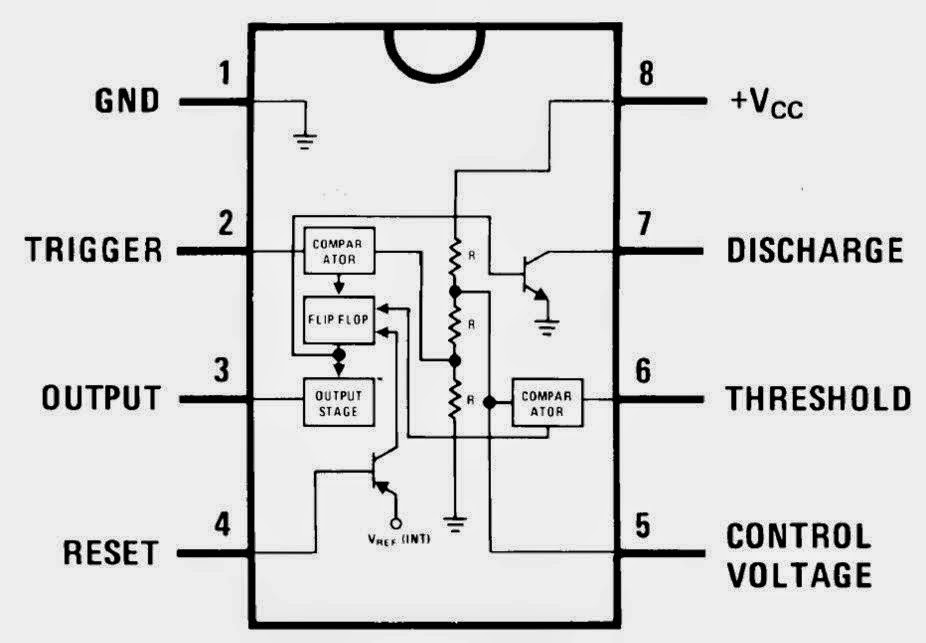

Explain the functional block diagram of Timer IC555

555 Timer IC: Internal Structure, Working, Pin Diagram and Description

IC 555 Pinouts and Working Explained

555 TIMER IC working - circuit diagram, waveforms and working Of 555

Astable Multivibrator using 555 Timer

timer ic 555 tester | Best Engineering Projects

IC 555 Pinouts, Astable, Monostable, Bistable Modes Explored

555 Timer Ic Schematic Diagram / The 555 timer can provide time delays

IC 555 - Datasheet, Rangkaian, Fungsi & Prinsip Kerja - Studi Elektronika
