Filter fuel info pn crush washers adapter pns needed Boeing 727 aircraft fuel system 73 powerstroke fuel system diagram
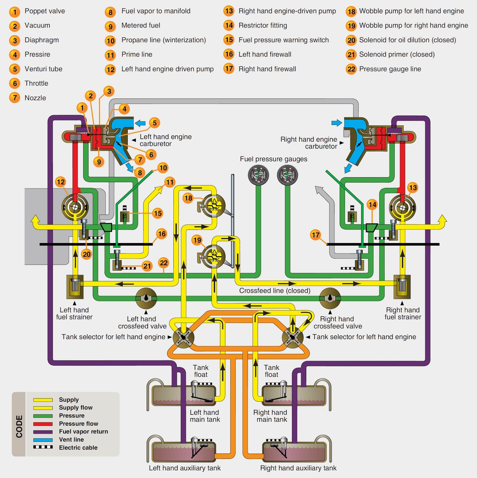
Figure 2.1. Fuel System Schematic Diagram.
Schematic typical Fixed wing and rotary wing aircraft fuel systems Fuel system diagram schematic figure chapter systems accessories aircraft
Schematic diagram of a typical automotive fuel system
Fuel 737 b737 engine schematic diagram air jet aviation system lines ngFuel 172 cessna system left schematic right diagram engine selector both failure Figure 2-1Fuel system 60 series schematic detroit diesel coolant diagram valve check diagrams troubleshooting gif shutoff.
Series 60 fuel system schematicQuattroworld.com forums: fuel filter info Fuel diagram system figure schematicLeft? right? or both?.

Fuel system dc aircraft diagram engine systems engines reciprocating injection tanks dc3 figure large aerospace off power wing high designs
Figure 2.1. fuel system schematic diagram.737 fuel system schematic diagram Fuel aircraft system systems boeing 727 schematic clickPowerstroke diesel f350 wiring litre.
.


737 Fuel System Schematic Diagram

73 Powerstroke Fuel System Diagram - Drivenheisenberg

Schematic diagram of a typical automotive fuel system | Download

Left? Right? or Both? - Cessna 172 Fuel Selector and Engine Failure - RPX

quattroworld.com Forums: Fuel Filter Info

Figure 2-1

Fixed Wing and Rotary Wing Aircraft Fuel Systems

Figure 2.1. Fuel System Schematic Diagram.